Week 9 · 3½ hours

The camera's point of view

The box you build: Perception geometry: where the camera sits on the car, and where on the road each pixel looks

What you will be able to do

  • Write the 3D ego frame and the camera's optical frame, build rotations about x, y and z with the right-hand rule, and say which way a positive pitch tips the camera

    Proof Practice problem 1 in the lab, and the quiz questions on the third axis, the pitch sign and the order of the turns

  • Build the camera mount as one 4 by 4 matrix, move points with w = 1 and directions with w = 0, and project road points into the picture exactly as the simulator does

    Proof Your T_ego_cam passes Exercise A, and your camera_mount (your world_to_ego with your mount) passes Exercise B on gentle

  • Send any pixel's ray to the road, and explain why a camera tipped up instead of down still drives straight but leaves gentle before the bend

    Proof Your ray_to_ground passes Exercise C, the break-it sections of the lab, and the quiz question on the mounted-wrong camera

Before this: Week 8 · Poses you can chain

Warm-up review

Nothing is due today. Pass a week's quiz and its questions come back here at growing intervals.

Lecture

You are bolting the camera onto the car. The spec sheet says it sits 1.4 m above the road at the front axle, tipped 5 degrees down, and every distance your perception box has measured since Your first perception box trusts those two numbers. Nobody has checked them against the picture. Given how the camera is mounted, where on the road is the thing a pixel sees?

By the end of this lesson you will write the camera's mount, where it sits on the car and how it is tipped, as one 4 by 4 matrix, T_ego_cam, and send any pixel's line of sight to the road with ray_to_ground. Then the simulator draws every camera picture through two pieces of your code, the world_to_ego you wrote in The view from the driver's seat and your mount, and the car still drives gentle.
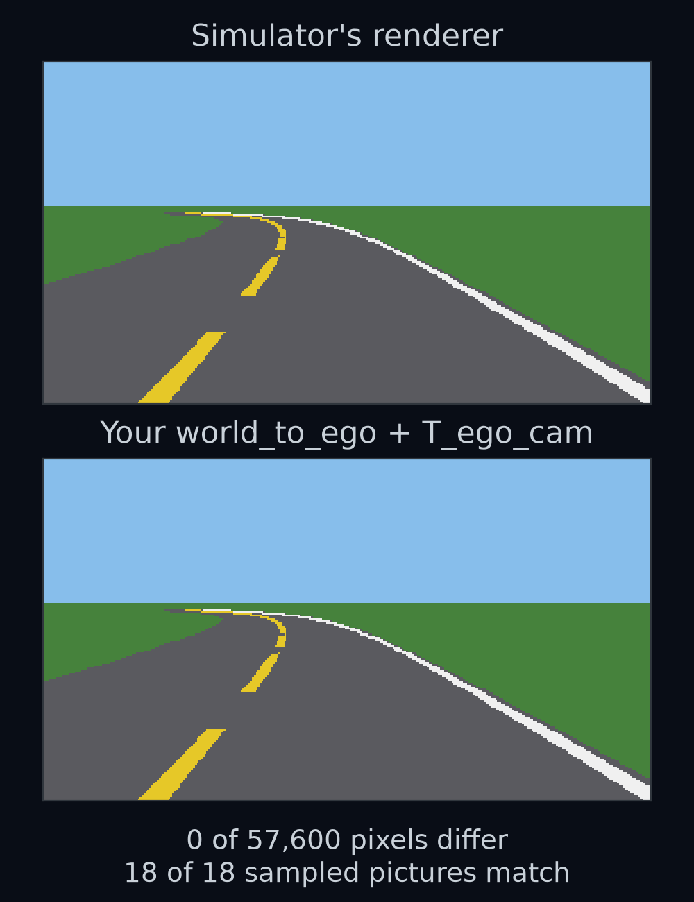
Top: one camera picture from the first bend of gentle, drawn by the simulator. Bottom: the same moment drawn through the world_to_ego you wrote and the mount you write in this lesson. In 18 pictures sampled along the lap, not one of the 57,600 pixels differs, and the lap matches step for step: 1778 steps, and a mean distance from the lane centre of 0.376 m. That 0.376 m is the provided car's own error: with the simulator's own camera it takes the same 1778 steps and gets the same 0.376 m, so a correct camera adds none.
Figure 1. Top: one camera picture from the first bend of gentle, drawn by the simulator. Bottom: the same moment drawn through the world_to_ego you wrote and the mount you write in this lesson. In 18 pictures sampled along the lap, not one of the 57,600 pixels differs, and the lap matches step for step: 1778 steps, and a mean distance from the lane centre of 0.376 m. That 0.376 m is the provided car's own error: with the simulator's own camera it takes the same 1778 steps and gets the same 0.376 m, so a correct camera adds none.

A third axis

The ego frame from The view from the driver's seat has two axes, x forward and y left, with its origin on the road under the front axle. The camera's lens is 1.4 m above that origin, and no amount of forward or left says "above". The ego frame needs a third axis, z, and you have to choose which way it points.

Up or down, both give three axes at right angles to each other. Engineers pick one with a rule: curl the fingers of your right hand from x toward y, and z is the way your thumb points. Curl them from forward toward left and your thumb points up. A frame built this way is called right-handed.

The same choice falls out of arithmetic. Positions and headings gave you the 2D cross product of two arrows a and b, axby−aybxa_x b_y - a_y b_x, read "a-x b-y minus a-y b-x", which is positive when b is to the left of a. In 3D the cross product of two arrows is a third arrow, at right angles to both, and its z part is exactly that 2D cross product. For forward, (1, 0, 0), and left, (0, 1, 0), the z part is 1 × 1 − 0 × 0 = 1.

Guess first: forward × left has a z part of +1. Which way does the whole arrow point? And which way does left × forward point?
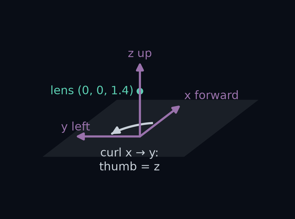
The ego frame drawn in 3D on the car: x forward along the car, y to its left and z up, all three from the origin on the road under the front axle. The lens sits on the z axis at (0, 0, 1.4). A curved arrow shows how the right hand's fingers curl from x toward y; the thumb would point along z, up.
Figure 2. The ego frame drawn in 3D on the car: x forward along the car, y to its left and z up, all three from the origin on the road under the front axle. The lens sits on the z axis at (0, 0, 1.4). A curved arrow shows how the right hand's fingers curl from x toward y; the thumb would point along z, up.

Answer: forward × left is (0, 0, 1), straight up, so z points up. Swap the order and left × forward is (0, 0, −1), straight down: like the 2D cross product, the 3D one changes sign when its two arrows swap. In this frame the lens is the point (0, 0, 1.4): 0 m ahead, 0 m left and 1.4 m up.

How we got the 3D cross product

Each part of a × b is a 2D cross product of the other two axes, taken in the order y then z, z then x, and x then y:

(a×b)x=aybz−azby(a×b)y=azbx−axbz(a×b)z=axby−aybx\begin{aligned} (\mathbf{a}\times\mathbf{b})_x &= a_y b_z - a_z b_y \\ (\mathbf{a}\times\mathbf{b})_y &= a_z b_x - a_x b_z \\ (\mathbf{a}\times\mathbf{b})_z &= a_x b_y - a_y b_x \end{aligned}

For a = (1, 0, 0) and b = (0, 1, 0): the x part is 0 × 0 − 0 × 1 = 0, the y part is 0 × 0 − 1 × 0 = 0, and the z part is 1 × 1 − 0 × 0 = 1. np.cross([1, 0, 0], [0, 1, 0]) gives [0, 0, 1], and np.cross([0, 1, 0], [1, 0, 0]) gives [0, 0, -1].

The rule also fixes which way a turn counts as positive. Point your right thumb along an axis, and your fingers curl the positive way round it. With the thumb up the z axis, the fingers carry forward toward left. So a positive turn about z is a turn to the left, the same direction as a positive yaw θ (read "theta"), the angle the car points in Positions and headings.
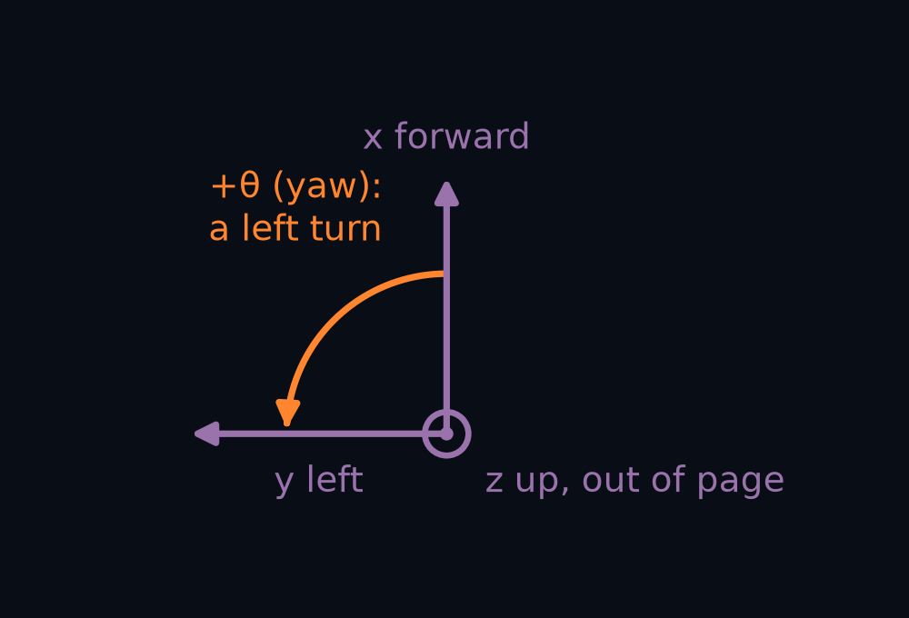
Looking down the z axis from above: the right thumb would point up out of the page, and a curved arrow shows how the fingers curl from x, forward, toward y, left. The curved arrow is the positive turn about z, a left turn, the direction of a positive yaw θ.
Figure 3. Looking down the z axis from above: the right thumb would point up out of the page, and a curved arrow shows how the fingers curl from x, forward, toward y, left. The curved arrow is the positive turn about z, a left turn, the direction of a positive yaw θ.

Turning about each axis

The camera is not level. It is tipped forward, so the lens looks a little down at the road. That tip is a turn about the car's y axis, the line through the camera from its right side to its left. A car can turn about each of its three axes, and each turn has a name: about z it yaws, turning left or right; about y it pitches, nose down or nose up; about x it rolls, leaning to one side.

You already have the yaw matrix. The view from the driver's seat turned 2D points with R(θ). A turn about z leaves the height alone, so the 3D yaw matrix is R(θ) with a row and a column added for z:

Rz(θ)=[cos⁡θ−sin⁡θ0sin⁡θcos⁡θ0001]\begin{aligned} &R_z(\theta) = \\ &\begin{bmatrix} \cos\theta & -\sin\theta & 0 \\ \sin\theta & \cos\theta & 0 \\ 0 & 0 & 1 \end{bmatrix} \end{aligned}

Read Rz(θ)R_z(\theta) "R z of theta", the turn by θ about z. 150 m along gentle the provided car's yaw is 0.591 rad. The top-left 2 by 2 of Rz(0.591)R_z(0.591) matches R(0.591) to the last digit, and up, (0, 0, 1), stays (0, 0, 1).

The tip is a turn about y by an angle φ, read "phi". Aircraft texts and vehicle texts that follow the ISO 8855 standard write roll as φ and pitch as θ; this course spent θ on the car's yaw first, so here φ is pitch. The same pattern of cos and sin moves to the x and z rows:

Ry(φ)=[cos⁡φ0sin⁡φ010−sin⁡φ0cos⁡φ]\begin{aligned} &R_y(\varphi) = \\ &\begin{bmatrix} \cos\varphi & 0 & \sin\varphi \\ 0 & 1 & 0 \\ -\sin\varphi & 0 & \cos\varphi \end{bmatrix} \end{aligned}

Your first perception box called this angle the pitch and wrote it p. From here on it is φ, because a bold p now names a point. The camera's pitch is still 5 degrees: φ = 0.0873 rad, with cos φ = 0.9962 and sin φ = 0.0872.

Guess first: put your right thumb along y, to the car's left. Does a positive turn about y tip the nose down or up?
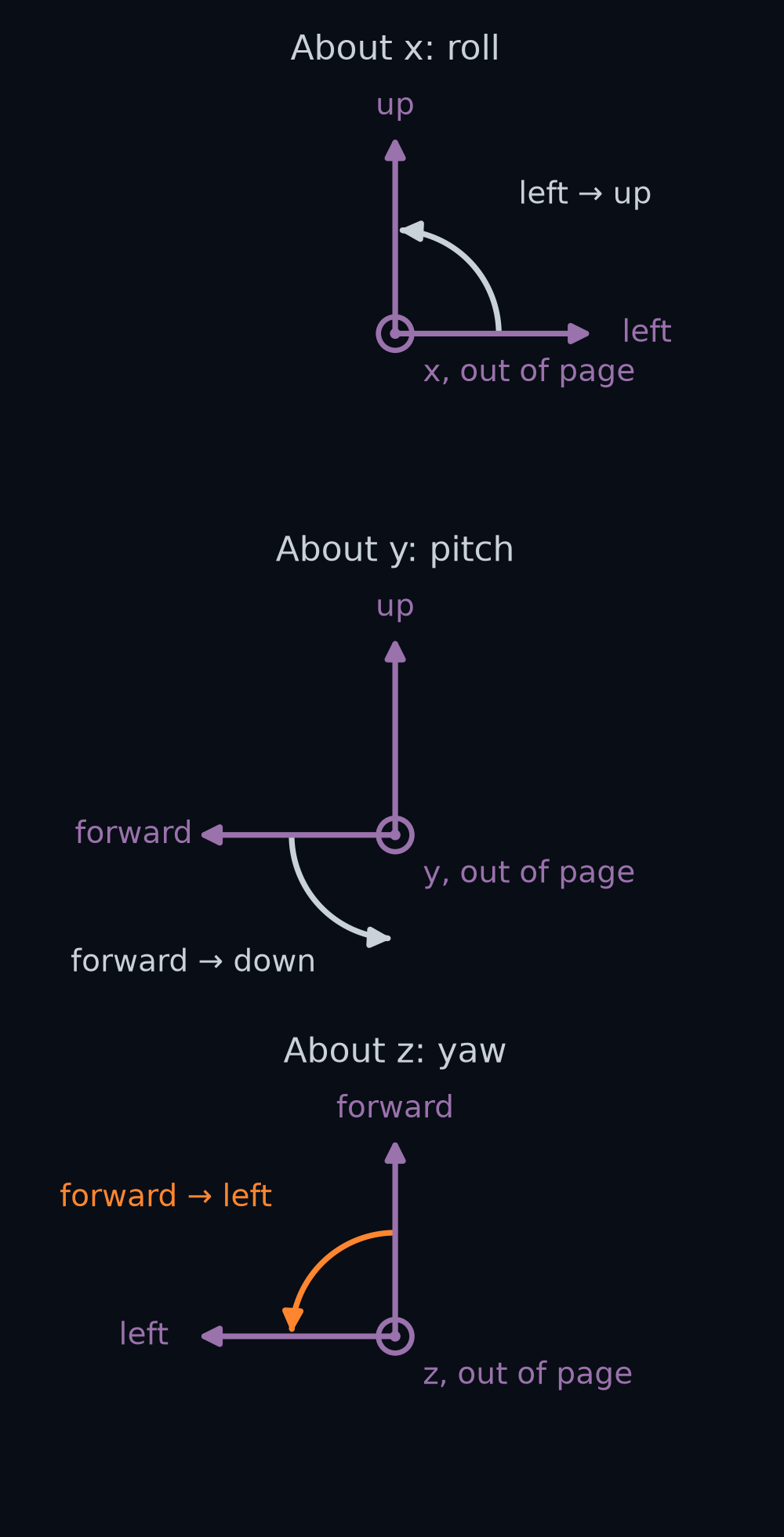
Three panels stacked, one per axis, each with a curved arrow for the positive turn: the fingers of the right hand curl that way when the thumb points along the axis. The pitch panel is seen from the car's left side, so forward points left; the other side views in this lesson are from the right. About x, roll: left tips toward up. About y, pitch: forward tips toward down. About z, yaw: forward turns toward left.
Figure 4. Three panels stacked, one per axis, each with a curved arrow for the positive turn: the fingers of the right hand curl that way when the thumb points along the axis. The pitch panel is seen from the car's left side, so forward points left; the other side views in this lesson are from the right. About x, roll: left tips toward up. About y, pitch: forward tips toward down. About z, yaw: forward turns toward left.

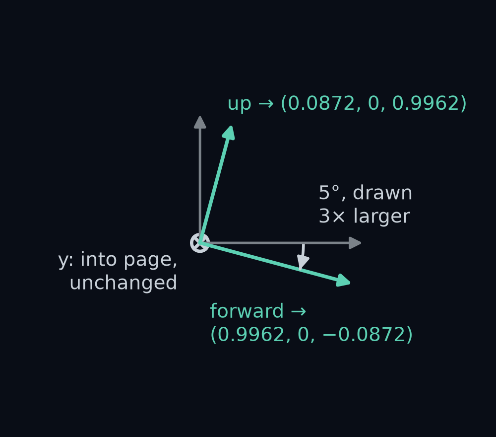
Answer: down. With your thumb pointing left, your fingers curl from up toward forward and from forward toward down. Multiply forward, (1, 0, 0), by Ry(φ)R_y(\varphi) and you get the matrix's first column, (cos φ, 0, −sin φ) = (0.9962, 0, −0.0872): the nose drops 0.0872 m for every 0.9962 m it reaches ahead. Positive pitch is nose down, which is why the 5 degrees in Your first perception box was a positive 0.0873 rad. Flip the sign and the nose rises, to (0.9962, 0, +0.0872).

The third turn, roll, leaves forward alone and tips left toward up. For a roll angle α, read "alpha":

Rx(α)=[1000cos⁡α−sin⁡α0sin⁡αcos⁡α]\begin{aligned} &R_x(\alpha) = \\ &\begin{bmatrix} 1 & 0 & 0 \\ 0 & \cos\alpha & -\sin\alpha \\ 0 & \sin\alpha & \cos\alpha \end{bmatrix} \end{aligned}

These are the three rotation matrices about the axes, and in code they are rot_x, rot_y and rot_z. Each takes an angle in radians and returns a 3 by 3. Each column is where one axis ends up: the first column of Ry(φ)R_y(\varphi) is where forward goes.

The columns of the pitch matrix drawn as arrows, seen from the car's right side. Forward, (1, 0, 0), turns to (0.9962, 0, −0.0872), dipping below level; up, (0, 0, 1), turns to (0.0872, 0, 0.9962), leaning forward; left, (0, 1, 0), points into the page and does not move. The 5 degree turn is drawn 3 times larger than it is.
Figure 5. The columns of the pitch matrix drawn as arrows, seen from the car's right side. Forward, (1, 0, 0), turns to (0.9962, 0, −0.0872), dipping below level; up, (0, 0, 1), turns to (0.0872, 0, 0.9962), leaning forward; left, (0, 1, 0), points into the page and does not move. The 5 degree turn is drawn 3 times larger than it is.

The camera's own axes

A camera does not count in forward, left and up. Its picture runs in columns and rows: the column number u grows to the right, the row number v grows downward, and the lens looks out along its axis. So the camera has its own frame, with x to the right across the picture, y down it, and z out through the lens. This is the optical frame, "cam" for short. In Week 1 a camera frame, and obs.frame, meant one picture, but here a frame is a set of axes; "camera picture" still means what the camera records.

For a camera that looked level and straight ahead, the two frames would differ only in their labels. Take a point 10 m ahead of the lens, 2 m left and level with it. In the optical frame it is 2 m to the left of the picture's x direction, so its cam x is −2; it is level, so its cam y is 0; and it is 10 m out along the lens, so its cam z is 10. The relabelling is one fixed matrix, B:

B=[0−1000−1100]B = \begin{bmatrix} 0 & -1 & 0 \\ 0 & 0 & -1 \\ 1 & 0 & 0 \end{bmatrix}

B times (10, 2, 0) is (−2, 0, 10). Each row of B picks one ego number: cam x is minus left, cam y is minus up, and cam z is forward.

B carries ego numbers to cam numbers. To carry cam numbers back, use its transpose, B⊤B^\top, read "B transpose": the same move that undid R(θ) in The view from the driver's seat. B⊤B^\top times B is the 3 by 3 identity, the matrix that changes nothing. The columns of B⊤B^\top are the cam axes written in ego numbers.
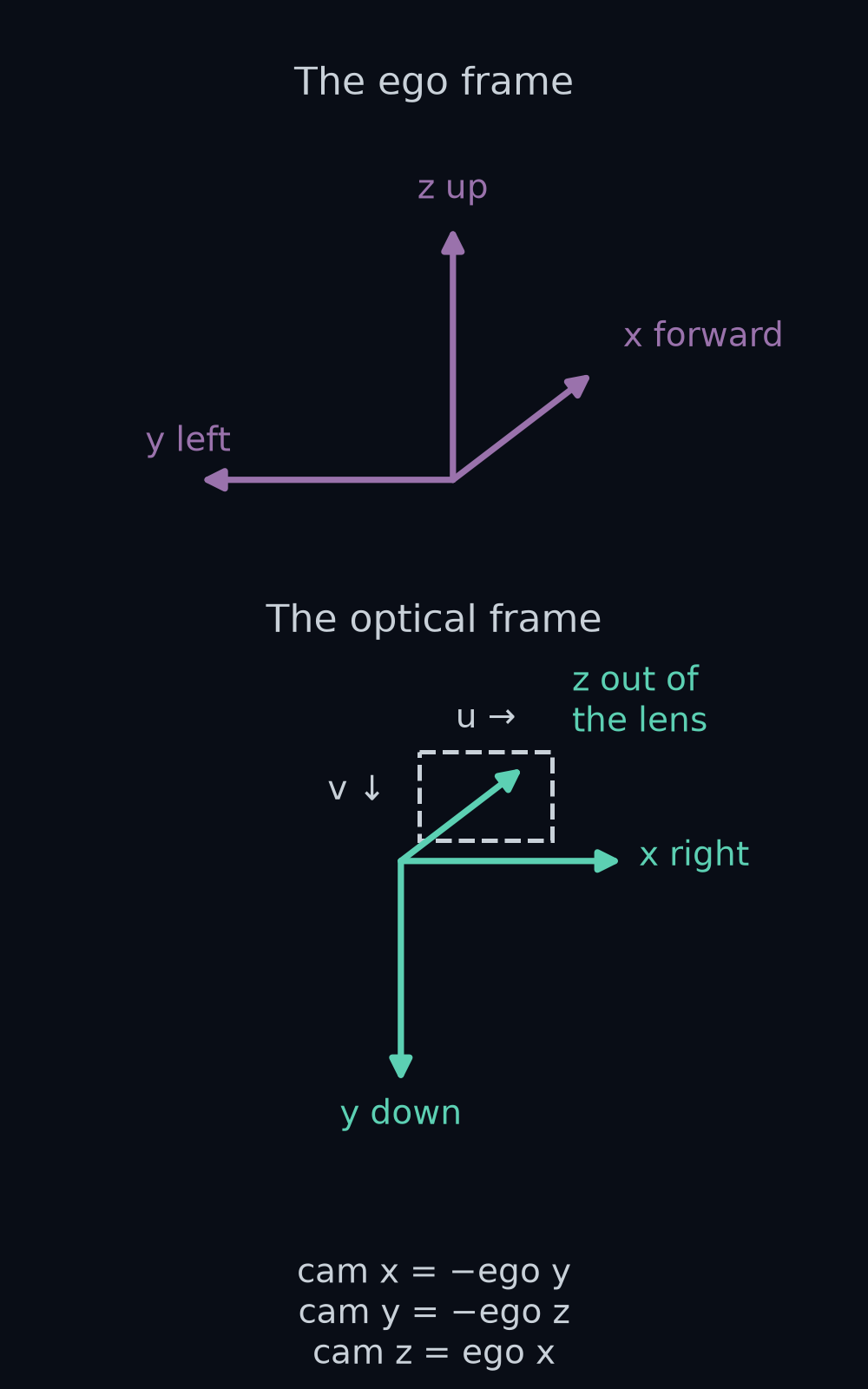
Two panels, stacked, at the lens of a level camera. Top: the ego frame, x forward, y left, z up. Bottom: the optical frame, x right, y down, z forward, out through the lens. The camera's x is the car's −y, its y is the car's −z, and its z is the car's x.
Figure 6. Two panels, stacked, at the lens of a level camera. Top: the ego frame, x forward, y left, z up. Bottom: the optical frame, x right, y down, z forward, out through the lens. The camera's x is the car's −y, its y is the car's −z, and its z is the car's x.

Now tip the camera. Start from the level camera, B⊤B^\top, then pitch it down by φ about the car's y axis:

Rego←cam=Ry(φ) B⊤R_{\text{ego}\leftarrow\text{cam}} = R_y(\varphi),B^\top

Read the subscript "ego from cam": this matrix takes a direction written in cam numbers and gives it in ego numbers, and the subscripts chain as in Poses you can chain. Its columns are the tipped camera's axes in the ego frame:

[0−0.08720.9962−1000−0.9962−0.0872]\begin{bmatrix} 0 & -0.0872 & 0.9962 \\ -1 & 0 & 0 \\ 0 & -0.9962 & -0.0872 \end{bmatrix}

Cam x is still the car's right, (0, −1, 0). Cam z, the lens axis, is (0.9962, 0, −0.0872), forward and dipping: the nose from the last section. Cam y, down the picture, is (−0.0872, 0, −0.9962), nearly straight down and leaning back by the same 5 degrees.

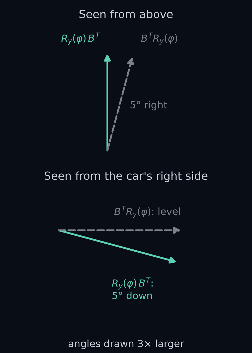
Guess first: Poses you can chain showed that order matters. Multiply the other way round, B⊤Ry(φ)B^\top R_y(\varphi). Which way does that camera look?

Two cameras' lens axes in two stacked panels: top, seen from above; bottom, seen from the car's right side. The correct camera, R_y(φ) times B transpose, looks straight ahead in the top panel and 5 degrees down in the bottom one. The wrong one, B transpose times R_y(φ), looks 0.0873 rad to the car's right in the top panel and level in the bottom one. The angles are drawn 3 times larger than they are.
Figure 7. Two cameras' lens axes in two stacked panels: top, seen from above; bottom, seen from the car's right side. The correct camera, R_y(φ) times B transpose, looks straight ahead in the top panel and 5 degrees down in the bottom one. The wrong one, B transpose times R_y(φ), looks 0.0873 rad to the car's right in the top panel and level in the bottom one. The angles are drawn 3 times larger than they are.

Answer: level, and 0.0873 rad, 5 degrees, to the right: its lens axis is (0.9962, −0.0872, 0). Written on the right, Ry(φ)R_y(\varphi) turns about the camera's y axis, which points down, so the 5 degrees became a turn of the head instead of a nod. The pitch has to turn the car's axes, so it goes on the left.

One 4×4 for the mount

The turn is half the mount. The other half is where the lens is: 1.4 m above the ego origin, t = (0, 0, 1.4), read "t", the mount's shift. Poses you can chain packed a 2D turn and shift into one 3 by 3 matrix with a trailing 1. In 3D the same trick gives a 4 by 4:

Tego←cam=[Rego←camt0    0    01]\begin{aligned} &T_{\text{ego}\leftarrow\text{cam}} = \\ &\begin{bmatrix} R_{\text{ego}\leftarrow\text{cam}} & \mathbf{t} \\ 0\;\;0\;\;0 & 1 \end{bmatrix} \end{aligned}

Read Tego←camT_{\text{ego}\leftarrow\text{cam}} "T, ego from cam". With h = 1.4 m for the height, and s = sin φ and c = cos φ to keep the matrix narrow, in full it is:

[0−sc0−10000−c−sh0001]\begin{bmatrix} 0 & -s & c & 0 \\ -1 & 0 & 0 & 0 \\ 0 & -c & -s & h \\ 0 & 0 & 0 & 1 \end{bmatrix}

To use it, write a point in the optical frame as four numbers, its three coordinates and a 1, and multiply. The lens itself, (0, 0, 0, 1), comes out at (0, 0, 1.4, 1): the trailing 1 picks up the last column. In code this is T_ego_cam(height_m, pitch_rad).
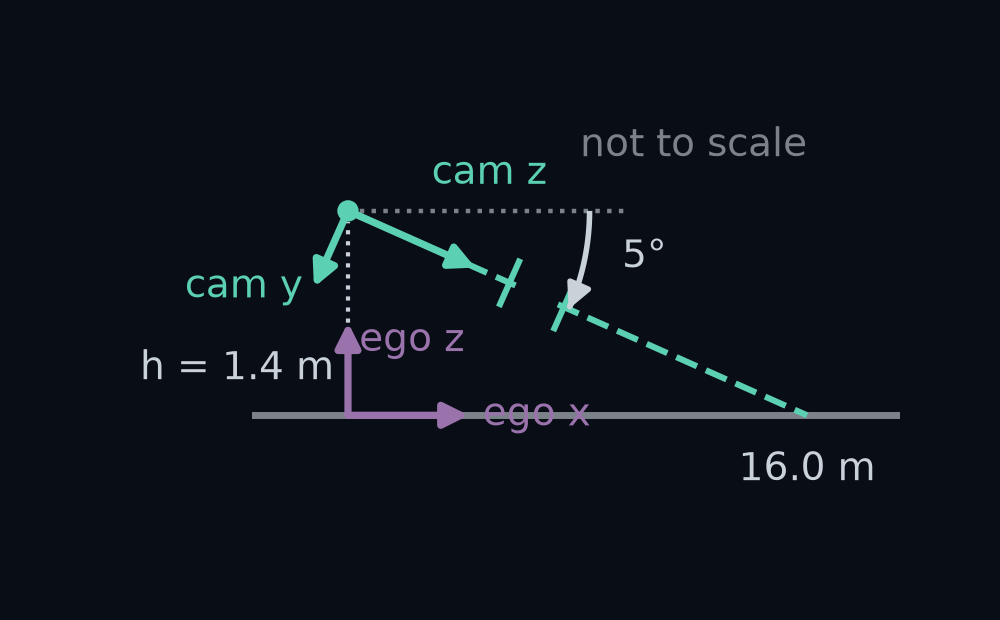
The mount seen from the car's right side, not to scale: the lens 1.4 m above the ego origin, its axis dipping 5 degrees below level and meeting the road 16.0 m ahead. The optical frame's z and y arrows are drawn at the lens, and the ego frame's x and z arrows at the origin.
Figure 8. The mount seen from the car's right side, not to scale: the lens 1.4 m above the ego origin, its axis dipping 5 degrees below level and meeting the road 16.0 m ahead. The optical frame's z and y arrows are drawn at the lens, and the ego frame's x and z arrows at the origin.

The renderer needs the other direction. It knows road points in the ego frame and must find them in the optical frame. That is the inverse, Tcam←egoT_{\text{cam}\leftarrow\text{ego}}, and Poses you can chain gave its closed form: transpose the turn, and make the new last column −Rego←cam⊤t-R_{\text{ego}\leftarrow\text{cam}}^\top\mathbf{t}. Here that column is (0, hcos⁡φ, hsin⁡φ)(0,\ h\cos\varphi,\ h\sin\varphi) = (0, 1.3947, 0.122). It says where the ego origin, the road right under the lens, sits in the optical frame: 1.3947 m down the picture and 0.122 m out along the lens axis.

How we got the inverse's last column

The rows of Rego←cam⊤R_{\text{ego}\leftarrow\text{cam}}^\top are the columns of Rego←camR_{\text{ego}\leftarrow\text{cam}}: (0, −1, 0), (−sin φ, 0, −cos φ) and (cos φ, 0, −sin φ). Multiply each by t = (0, 0, h):

(0, −hcos⁡φ, −hsin⁡φ)\begin{aligned} &(0,\ -h\cos\varphi,\ -h\sin\varphi) \end{aligned}

Change the signs and you have (0, hcos⁡φ, hsin⁡φ)(0,\ h\cos\varphi,\ h\sin\varphi): 1.4 × 0.9962 = 1.3947 and 1.4 × 0.0872 = 0.122. Multiplying Tcam←egoT_{\text{cam}\leftarrow\text{ego}} by Tego←camT_{\text{ego}\leftarrow\text{cam}} gives the 4 by 4 identity to within 2.3×10−182.3\times10^{-18}, and the closed form matches np.linalg.inv exactly.

The last step, from the optical frame to a pixel, belongs to the camera, and it is given. A point at cam (x, y, z) lands at

u=cx+f x/zv=cy+f y/z\begin{aligned} u &= c_x + f\,x / z \\ v &= c_y + f\,y / z \end{aligned}

with focal length f = 160 px and middle column and row (cx,cy)(c_x, c_y) = (159.5, 89.5), read "c-x, c-y", the numbers from Your first perception box. The module Camera geometry opens this step up; here you use it as it is.

Work one point by hand: the road 10 m straight ahead, ego (10, 0, 0). The rows of Tcam←egoT_{\text{cam}\leftarrow\text{ego}} give cam x = 0, cam y = −10 × 0.0872 + 1.3947 ≈ 0.523, and cam z = 10 × 0.9962 + 0.122 = 10.084. So u = 159.5, and v = 89.5 + 160 × 0.523 / 10.084 ≈ 97.8. The renderer's ground_to_pixel(10, 0) says (159.5, 97.8002).

Guess first: push 200 random road points, 2 to 60 m ahead and up to 8 m to either side, through your Tcam←egoT_{\text{cam}\leftarrow\text{ego}} and the pinhole step. How far from the renderer's own pixels will they land?
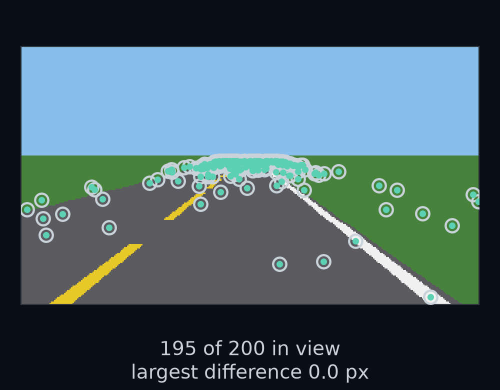
A camera picture of the empty road with 195 of the 200 random road points, the ones that fall inside the 320 by 180 picture, drawn twice: open circles where the renderer's ground_to_pixel puts them, and dots where your 4×4 and the pinhole step put them. Every dot sits in the centre of its circle.
Figure 9. A camera picture of the empty road with 195 of the 200 random road points, the ones that fall inside the 320 by 180 picture, drawn twice: open circles where the renderer's ground_to_pixel puts them, and dots where your 4×4 and the pinhole step put them. Every dot sits in the centre of its circle.

Answer: 0.0 px, in u and in v. The renderer's formula is this same turn, shift and divide, written out for one camera. The same arithmetic shows what the camera cannot see. The road right under the lens, cam (0, 1.3947, 0.122), would land at row 89.5 + 160 × 1.3947 / 0.122, about 1918, far below the picture's last row, 179. So the bottom row sees the road 2.06 m ahead, and no pixel sees the road right under the lens.
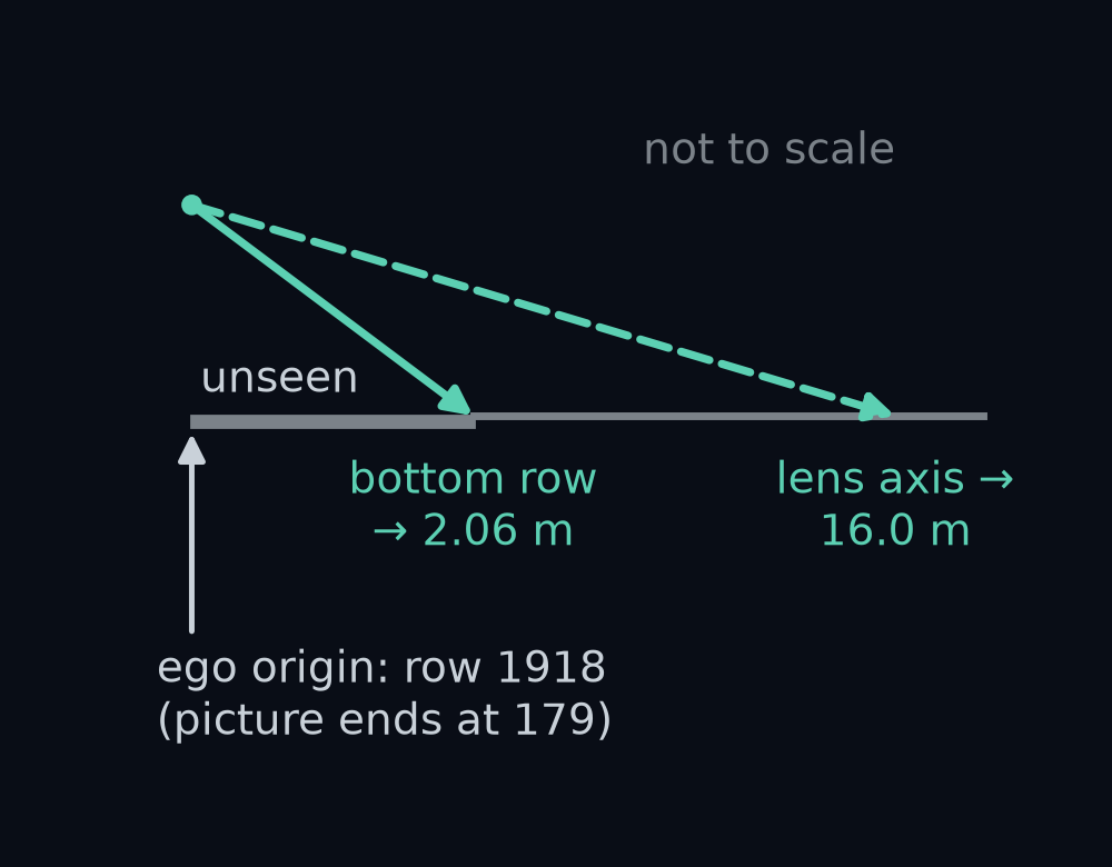
The mount from the car's right side, not to scale. The ray through the bottom row of the picture leaves the lens and meets the road 2.06 m ahead, and the lens axis meets it 16.0 m ahead. The road from the ego origin to 2.06 m ahead is shaded grey: no pixel sees it. To be seen, the ego origin would need row 1918, and the picture ends at row 179.
Figure 10. The mount from the car's right side, not to scale. The ray through the bottom row of the picture leaves the lens and meets the road 2.06 m ahead, and the lens axis meets it 16.0 m ahead. The road from the ego origin to 2.06 m ahead is shaded grey: no pixel sees it. To be seen, the ego origin would need row 1918, and the picture ends at row 179.

Points move, directions only turn

The lens axis is not a place. It is a direction: it says which way the camera looks, not where anything is. Where does it point in the ego frame?

Moving between frames treats the two differently. A point turns and shifts, because the origin moved. A direction only turns: the direction "straight down the lane" is the same whether you stand at the lens or at the ego origin.

The fourth number does this for you. Write a point with a 1 at the end, the trailing 1 from Poses you can chain, and the multiply adds the last column, t. Write a direction with a 0 at the end, and the last column is multiplied by 0 and drops out. That fourth number is called w: w = 1 for a point, w = 0 for a direction.

The lens axis in the optical frame is (0, 0, 1). As a direction, with w = 0, the mount turns it to (0.9962, 0, −0.0872), the third column of the turn. As a point, with w = 1, it comes out at (0.9962, 0, 1.3128): the place 1 m out along the axis from the lens, a fine answer to a different question.

Guess first: treat (0.9962, 0, 1.3128) as the direction anyway. Which way does the camera now seem to look? And how many of the picture's 57,600 pixel rays would point down at the road?
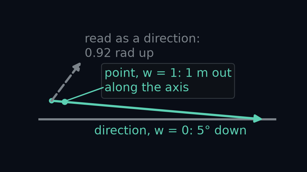
The mount from the car's right side. Drawn from the lens, the direction (0.9962, 0, −0.0872) dips 5 degrees below level and meets the road ahead. The point (0.9962, 0, 1.3128) sits 1 m out along that axis. Read as a direction from the lens instead, it climbs 0.92 rad above level and never comes down.
Figure 11. The mount from the car's right side. Drawn from the lens, the direction (0.9962, 0, −0.0872) dips 5 degrees below level and meets the road ahead. The point (0.9962, 0, 1.3128) sits 1 m out along that axis. Read as a direction from the lens instead, it climbs 0.92 rad above level and never comes down.

Answer: 0.92 rad, 53 degrees, above level, and none of the 57,600. Every pixel's ray picks up the lens's 1.4 m of height as if it belonged to the direction, so even the bottom row's ray climbs. With w = 0, every pixel from row 76 down, 33,280 of them, meets the road. In code the two moves are transform_points(T, p), which uses w = 1, and transform_directions(T, r), which uses w = 0 and so only the turn.

The same mistake moves the horizon. The car's forward direction, (1, 0, 0), sent into the optical frame with w = 0, is (0, −0.0872, 0.9962). The pinhole step puts it at row 89.5 + 160 × (−0.0872 / 0.9962) = 75.5, the horizon row of Your first perception box, where the flat road meets the sky. With w = 1 it lands at row 276.6, below the bottom of the picture.
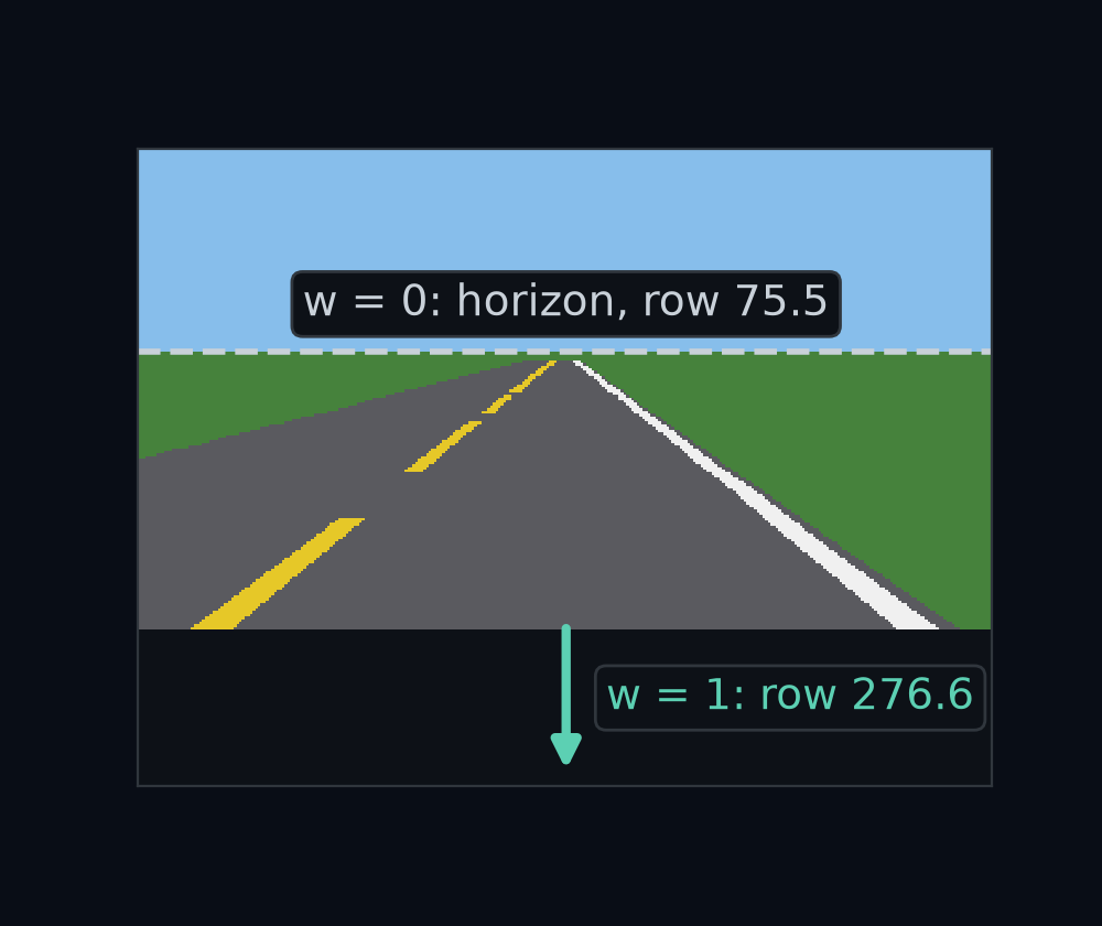
A camera picture of the empty road with two marks on the middle column. A dashed line at row 75.5, labelled w = 0, is where the car's forward direction lands, the horizon. An arrow off the bottom edge, labelled w = 1, points to row 276.6, where the same direction lands when it is wrongly shifted by the mount.
Figure 12. A camera picture of the empty road with two marks on the middle column. A dashed line at row 75.5, labelled w = 0, is where the car's forward direction lands, the horizon. An arrow off the bottom edge, labelled w = 1, points to row 276.6, where the same direction lands when it is wrongly shifted by the mount.

Where a pixel's ray meets the road

Back to the question this lesson opened with. In the first picture of gentle, the white edge line crosses row 150 between columns 249 and 260, centred on column 254.5. Where on the road is that paint?

Each pixel sees along one ray, a line out of the lens. The pixel's ray in the optical frame is given by pixel_ray(camera, u, v):

rcam=(a, b, 1)a=(u−cx)/fb=(v−cy)/f\begin{aligned} \mathbf{r}_{\text{cam}} &= (a,\ b,\ 1) \\ a &= (u - c_x) / f \\ b &= (v - c_y) / f \end{aligned}

Read a and b as how far right of the middle column and how far below the middle row the pixel is, in units of f. For column 254.5 and row 150, a = 95 / 160 = 0.5937 and b = 60.5 / 160 = 0.3781.

A ray is a direction, so it goes into the ego frame with w = 0: r = Rego←cam rcamR_{\text{ego}\leftarrow\text{cam}},\mathbf{r}_{\text{cam}}, read "r", the ray in ego numbers:

rx=cos⁡φ−bsin⁡φry=−arz=−(sin⁡φ+bcos⁡φ)\begin{aligned} r_x &= \cos\varphi - b\sin\varphi \\ r_y &= -a \\ r_z &= -(\sin\varphi + b\cos\varphi) \end{aligned}

For the paint, r = (0.9632, −0.5937, −0.4638): forward, to the right and down. Now walk along it from the lens, t. After λ steps, read "lambda", you are at g = t + λr, read "g" for ground. Each step drops 0.4638 m and the lens starts 1.4 m up, so you reach the road, height 0, when

λ=−tz/rz=1.4/0.4638≈3.018\begin{aligned} \lambda &= -t_z / r_z \\ &= 1.4 / 0.4638 \\ &\approx 3.018 \end{aligned}

That puts the paint at g = (3.018 × 0.9632, 3.018 × −0.5937, 0) = (2.907, −1.792, 0): 2.907 m ahead and 1.792 m to the right, on the white line, which the road paints 1.7 to 1.9 m right of the lane centre.
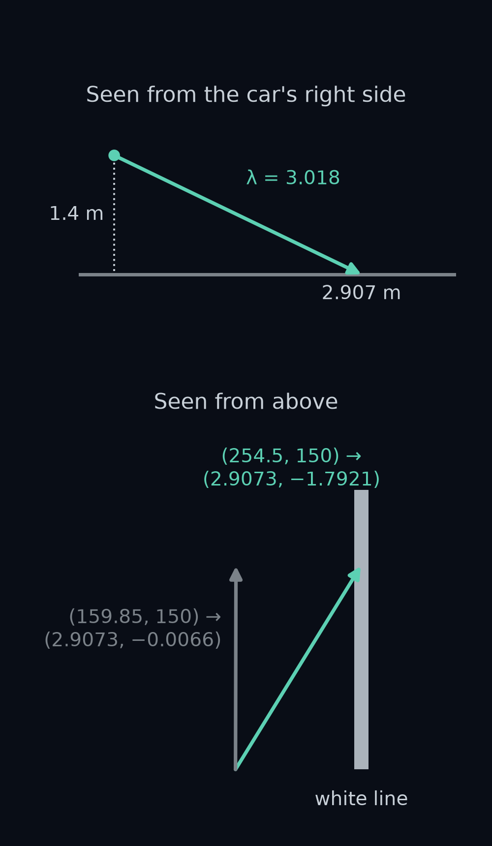
The ray from the lens through the paint pixel, (254.5, 150), in two stacked panels. Top, from the car's right side: it leaves the lens 1.4 m up and meets the road 2.907 m ahead. Bottom, from above: it heads to the right of straight ahead and lands 1.792 m right, on the white line. Drawn with it, the ray through pixel (159.85, 150) lands at (2.9073, −0.0066).
Figure 13. The ray from the lens through the paint pixel, (254.5, 150), in two stacked panels. Top, from the car's right side: it leaves the lens 1.4 m up and meets the road 2.907 m ahead. Bottom, from above: it heads to the right of straight ahead and lands 1.792 m right, on the white line. Drawn with it, the ray through pixel (159.85, 150) lands at (2.9073, −0.0066).

λ is not new. The ray's cam z is 1, so λ steps along it carry you λ metres out along the lens axis, and 3.0183 is the Z of Your first perception box, row 150's road point measured along the camera's axis. If rzr_z is 0 or positive, the ray is level or climbing and never meets the road. That is every pixel above the horizon, and there the answer is NaN. Finding where a line meets a flat surface this way is called ray–plane intersection, and ray_to_ground(T_ego_cam, ray_cam) does it for the road, the plane z = 0.

Guess first: the renderer's pixel_to_ground is a closed formula written for this one camera, while ray_to_ground works for any mount. Over 200 random pixels below the horizon, how far apart will their answers be?
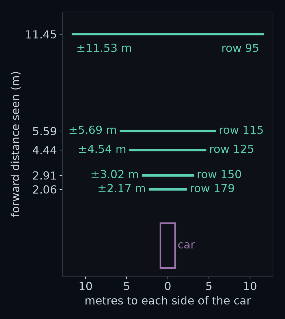
Every pixel of rows 179, 150, 125, 115 and 95 sent to the road through ray_to_ground, seen from above. Each row lands on a straight line across the road at one distance: 2.058 m, 2.907 m, 4.438 m, 5.592 m and 11.454 m ahead. The lines get wider with distance: row 150 spans 3.018 m to either side, row 95 spans 11.532 m.
Figure 14. Every pixel of rows 179, 150, 125, 115 and 95 sent to the road through ray_to_ground, seen from above. Each row lands on a straight line across the road at one distance: 2.058 m, 2.907 m, 4.438 m, 5.592 m and 11.454 m ahead. The lines get wider with distance: row 150 spans 3.018 m to either side, row 95 spans 11.532 m.

Answer: 0.0 m, forward and sideways, and 200 random pixels above the horizon all give NaN. The figure shows why "a row is a distance" from Your first perception box holds across the whole row. The forward part, λrx\lambda r_x, uses only b, the row. The sideways part, −λa-\lambda a, grows in step with the column. In the middle column, where a = 0, the forward distance is h/tan⁡(φ+arctan⁡b)h / \tan(\varphi + \arctan b), the formula from that lesson: 2.9073 m for row 150 and 11.4537 m for row 95.

How we got the middle-column formula

Write β, read "beta", for arctan b, so b = sin β / cos β. With a = 0, the forward distance is λrx\lambda r_x and λ = h / (−r_z):

x=h cos⁡φ−bsin⁡φsin⁡φ+bcos⁡φ=h cos⁡(φ+β)sin⁡(φ+β)=h/tan⁡(φ+β)\begin{aligned} x &= h\,\frac{\cos\varphi - b\sin\varphi}{\sin\varphi + b\cos\varphi} \\ &= h\,\frac{\cos(\varphi+\beta)}{\sin(\varphi+\beta)} \\ &= h / \tan(\varphi + \beta) \end{aligned}

The middle step multiplies top and bottom by cos β and uses the angle-sum rules from school trigonometry, cos φ cos β − sin φ sin β = cos(φ + β) and sin φ cos β + cos φ sin β = sin(φ + β). For row 150, φ + β = 0.0873 + 0.3615 = 0.4488 rad, and 1.4 / tan 0.4488 = 2.9073 m.

A camera mounted wrong

Now the bracket. Suppose it goes on so that the camera is tipped 5 degrees up instead of down. The perception box does not know. It still turns pixels into road points as if the camera were tipped 5 degrees down, so the picture and the measurement disagree.

Guess first: tilt the camera 5° up instead of down. Which road will show it, straight or gentle?
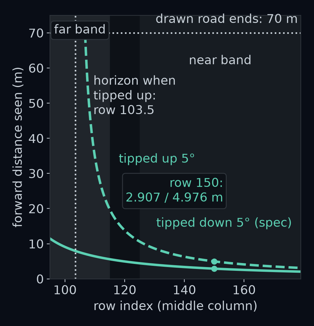
The distance ahead that each row sees in the middle column, with the camera tipped 5 degrees down, as specified, and 5 degrees up. Row 150 sees 2.907 m with the spec and 4.976 m tipped up. Tipped up, the horizon drops from row 75.5 to row 103.5. The far band, rows 95 to 115, should see 5.59 m to 11.45 m; tipped up, only its rows from 107 to 115 see road, from 70 m, the end of the drawn road, down to 19.75 m.
Figure 15. The distance ahead that each row sees in the middle column, with the camera tipped 5 degrees down, as specified, and 5 degrees up. Row 150 sees 2.907 m with the spec and 4.976 m tipped up. Tipped up, the horizon drops from row 75.5 to row 103.5. The far band, rows 95 to 115, should see 5.59 m to 11.45 m; tipped up, only its rows from 107 to 115 see road, from 70 m, the end of the drawn road, down to 19.75 m.

The box still places those far-band rows 5.59 m to 7.11 m ahead, so road truly 70 m away is put 7.11 m away. Every row lies about its distance. What matters is whether the lie changes the two numbers the controller gets.
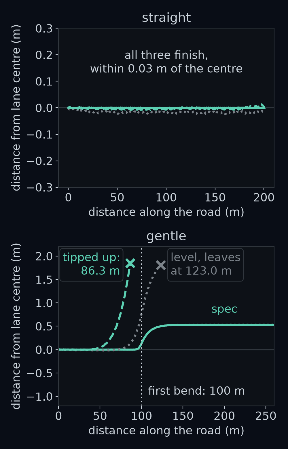
Distance from the lane centre against distance along the road for the provided car with the renderer's camera tipped 5 degrees down, level and 5 degrees up, on straight (top) and on gentle (bottom). Same car, same seed, same speed. On straight all three finish. On gentle the tipped-up camera leaves the lane to the left at 86.3 m, before the first bend starts at 100 m, and the level camera leaves at 123.0 m.
Figure 16. Distance from the lane centre against distance along the road for the provided car with the renderer's camera tipped 5 degrees down, level and 5 degrees up, on straight (top) and on gentle (bottom). Same car, same seed, same speed. On straight all three finish. On gentle the tipped-up camera leaves the lane to the left at 86.3 m, before the first bend starts at 100 m, and the level camera leaves at 123.0 m.

Answer: only gentle. Tipped up, the car finishes straight with a mean distance from the lane centre of 0.004 m, against 0.000 m with the spec mount. It leaves gentle on the left at 86.3 m, 10.85 s in, 13.7 m before the first bend even starts. A level camera finishes straight with 0.016 m and leaves gentle at 123.0 m, 23 m into the bend.

Why before the bend? Hold the car on the lane centre of gentle, pointing along it, and read the box. With the spec camera its heading ψ (read "psi"; the yaw minus the lane's direction, wrapped, as in Your first perception box) stays within 0.002 rad of the truth, 0, all the way. Tipped up, it reads −0.002 rad at 20 m along, where the bend is still out of sight, then grows as the bend comes into view.
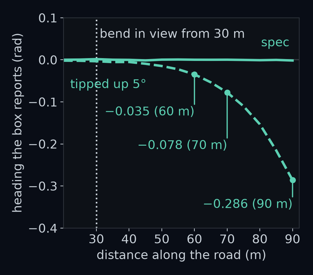
The box's heading for a car held on the lane centre of gentle and pointing along it, from 20 m to 90 m along. With the spec camera it stays within 0.002 rad of 0. With the camera tipped 5 degrees up it falls to −0.035 rad at 60 m, −0.078 rad at 70 m and −0.286 rad at 90 m: the box says the car points right of the lane when it points straight along it. The first bend starts at 100 m.
Figure 17. The box's heading for a car held on the lane centre of gentle and pointing along it, from 20 m to 90 m along. With the spec camera it stays within 0.002 rad of 0. With the camera tipped 5 degrees up it falls to −0.035 rad at 60 m, −0.078 rad at 70 m and −0.286 rad at 90 m: the box says the car points right of the lane when it points straight along it. The first bend starts at 100 m.

The road is drawn 70 m ahead, so the bend is in the picture from 30 m along. Tipped up, the far band sees the start of the bend 20 to 70 m ahead but places it 5.6 to 7.1 m ahead. A lane that will start curving left 60 m away looks like a lane swinging sharply left right in front of the car. The box reports that the car points right of the lane, the controller steers left, and the car drifts left until it leaves.

The drive itself shows the same split. At 70 m along, the car is truly 0.505 m left and points 0.038 rad left. Through the spec camera, that same pose reads 0.498 m and +0.040 rad. Through the tipped-up camera it reads 0.744 m and −0.102 rad: right about the side, wrong about the heading.

In the lab you swap your world_to_ego and your mount into the renderer. With the right sign, no sampled picture differs. Flip the sign of φ inside your T_ego_cam and all 18 pictures differ and the car would leave gentle at 86.3 m, exactly like the bracket tipped up: a sign error in the mount is a camera mounted wrong. (The grader catches both first, saying your camera tips up or your turn is a roll, before any picture or drive.) Put rot_x where rot_y belongs and the camera rolls 5 degrees instead of pitching. It finishes straight 0.341 m right of the centre, after a mean of 0.314 m, and leaves gentle at 119.1 m.
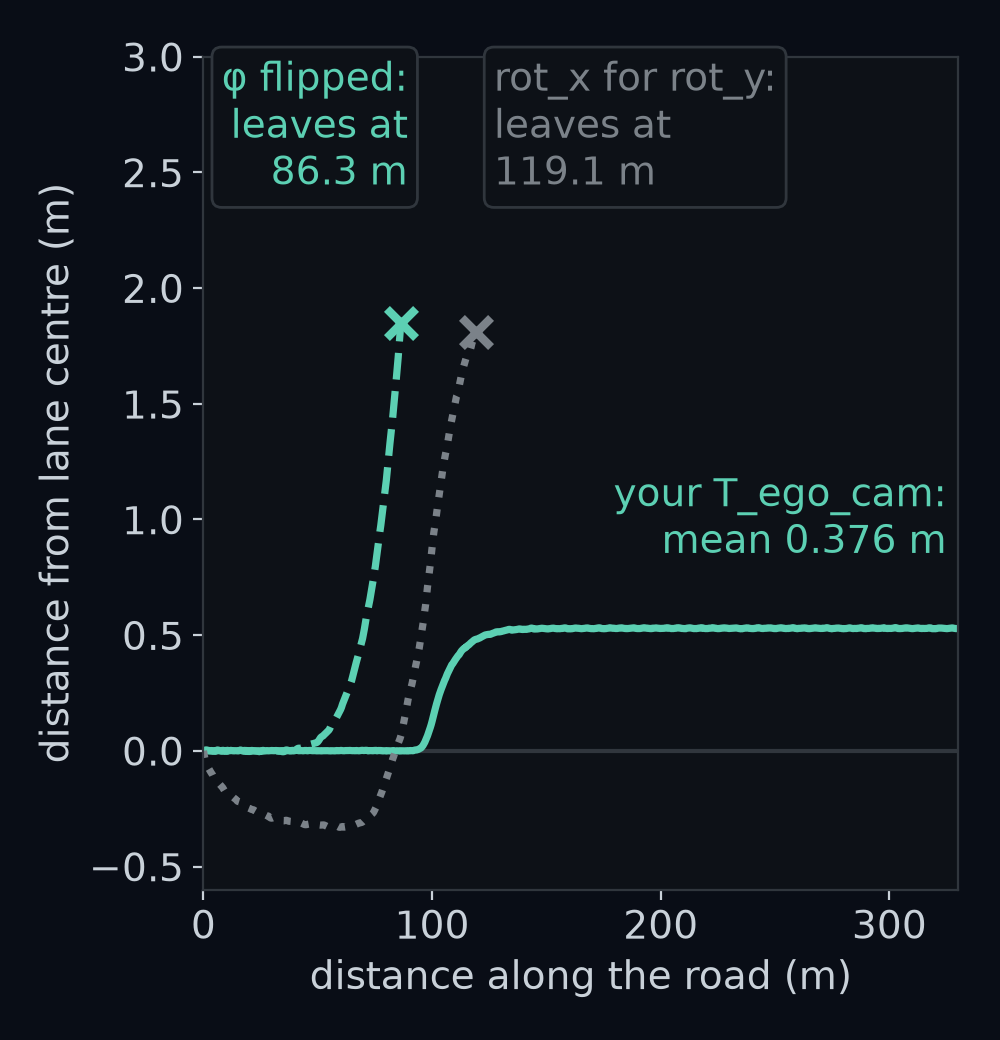
Distance from the lane centre against distance along gentle for three mounts written as code and swapped into the renderer: your T_ego_cam, which finishes with a mean of 0.376 m; the same with the sign of φ flipped, which leaves at 86.3 m; and rot_x in place of rot_y, which leaves at 119.1 m. The 0.376 m is the provided car's own error: the simulator's own camera gives the same 1778 steps and the same 0.376 m.
Figure 18. Distance from the lane centre against distance along gentle for three mounts written as code and swapped into the renderer: your T_ego_cam, which finishes with a mean of 0.376 m; the same with the sign of φ flipped, which leaves at 86.3 m; and rot_x in place of rot_y, which leaves at 119.1 m. The 0.376 m is the provided car's own error: the simulator's own camera gives the same 1778 steps and the same 0.376 m.

Height errors are kinder. A camera truly 1.2 m up sees row 150's road 2.492 m ahead. The box assumes 1.4 m and follows the same ray to 2.907 m, 7/6 as far, because the two triangles have the same shape.
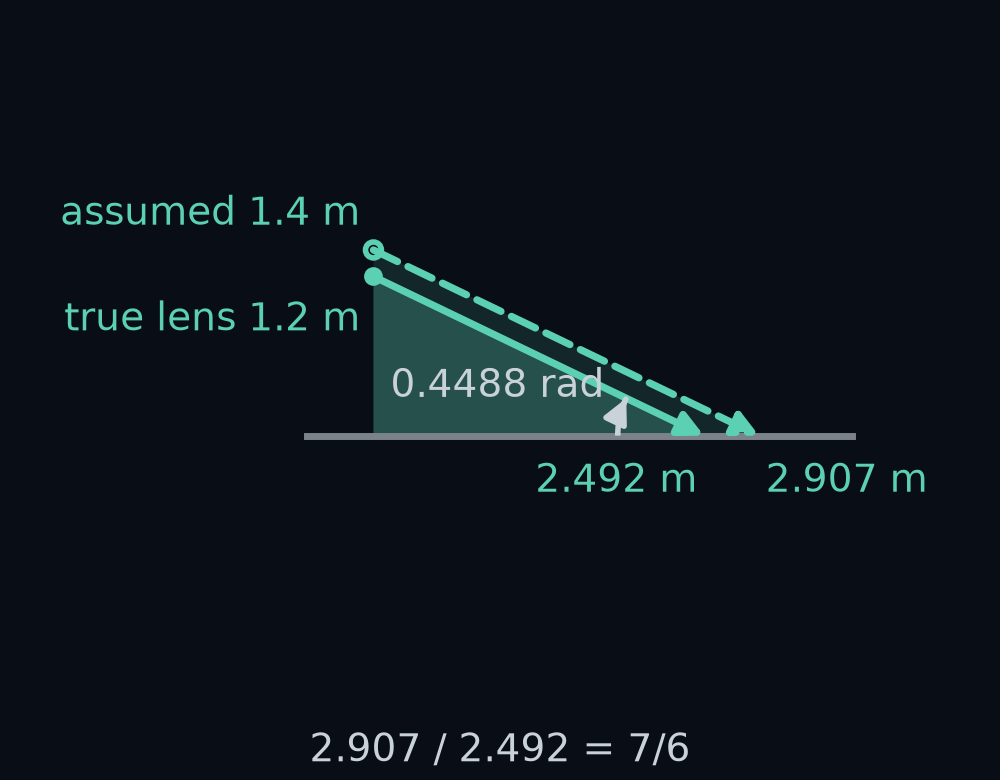
The ray through row 150's middle column, from the car's right side, drawn from two lens heights at the same angle, 0.4488 rad below level. From a lens truly 1.2 m up it meets the road 2.492 m ahead. From the 1.4 m the box assumes it meets the road 2.907 m ahead. The two triangles have the same shape, so 2.907 is 7/6 of 2.492, as 1.4 is 7/6 of 1.2.
Figure 19. The ray through row 150's middle column, from the car's right side, drawn from two lens heights at the same angle, 0.4488 rad below level. From a lens truly 1.2 m up it meets the road 2.492 m ahead. From the 1.4 m the box assumes it meets the road 2.907 m ahead. The two triangles have the same shape, so 2.907 is 7/6 of 2.492, as 1.4 is 7/6 of 1.2.

Every road point scales by 7/6, forward and sideways alike, and scaling keeps angles. For a car truly 0.4 m left and pointing 0.05 rad left, the box reads its heading as 0.0519 rad through the 1.2 m camera and 0.0512 rad through the spec camera. The car finishes gentle with a mean distance from the centre of 0.286 m at 1.2 m and 0.472 m at 1.6 m, against 0.376 m for the spec mount.

Measuring the mount's real height and pitch, so that the box's numbers match the picture, is called calibration. The first challenge problem does it with four painted marks.

Recap

  • The ego frame is right-handed in 3D: x forward, y left, z up. Positive pitch, about y, is nose down; the camera's φ is 0.0873 rad.
  • The mount Tego←camT_{\text{ego}\leftarrow\text{cam}} packs Ry(φ) B⊤R_y(\varphi),B^\top and t = (0, 0, 1.4). Points take w = 1, directions w = 0, and with the pinhole step it reproduces the renderer to 0.0 px.
  • A pixel's ray meets the road at λ = −t_z / r_z. Flip the pitch sign and the car still drives straight, but leaves gentle at 86.3 m.
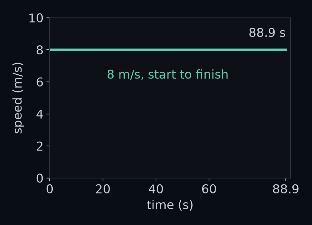
The provided car's speed through one lap of gentle, plotted against time: a flat line at 8 m/s from the first step to the last, 88.9 s later.
Figure 20. The provided car's speed through one lap of gentle, plotted against time: a flat line at 8 m/s from the first step to the last, 88.9 s later.

Every lap in this course, on every road, has run at 8 m/s. The scenario starts the car at that speed, and the provided speed controller holds it there, bend or no bend. Who chose 8 m/s, and how would the car reach a different speed, hold it, or slow down for a bend? That is the next module, Longitudinal control and vehicle motion.

Challenge problems

  1. Calibrate the mount. You paint four marks on flat ground at (3, 1), (3, −1), (8, 1) and (8, −1) m, forward and left of the ego origin, and find them in the picture: the near pair in row 147.789 and the far pair in row 103.291. Recover the pitch and the height, knowing neither. Hint: for a guessed pitch, a mark x m ahead in a row with ratio b implies a height of xtan⁡(φ+arctan⁡b)x\tan(\varphi + \arctan b). Only the right pitch makes the near and far marks imply the same height.
  2. One pixel of error. Your mark finder reads every row 1 px too large. How far off is the pitch you recover? Compare it with the angle between the rays of two neighbouring rows.
  3. The w = 1 ray. Show that with w = 1, no pixel ray in the picture points down. From which row would a ray have to come?
  4. A low camera. Show that a camera truly h m up, read as if 1.4 m up, places every road point at 1.4 / h times its true distance, forward and sideways alike.
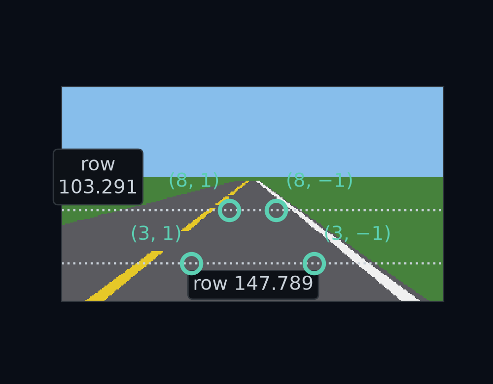
The empty road as the spec camera sees it, with the four painted marks circled. The near pair, 3 m ahead and 1 m to either side, sits in row 147.789, at columns 108.063 and 210.937. The far pair, 8 m ahead, sits in row 103.291, at columns 139.726 and 179.274.
Figure 21. The empty road as the spec camera sees it, with the four painted marks circled. The near pair, 3 m ahead and 1 m to either side, sits in row 147.789, at columns 108.063 and 210.937. The far pair, 8 m ahead, sits in row 103.291, at columns 139.726 and 179.274.
Answers

1. Call the gap the far pair's implied height minus the near pair's. At pitch 0 the near marks imply 1.0929 m and the far marks 0.6895 m, a gap of −0.4034 m. The gap is −0.1715 m at φ = 0.05 and +0.2873 m at φ = 0.15, so the answer lies between. Bisection halves that bracket again and again, each time keeping the half whose ends have gaps of opposite sign. Halve it until the bracket is tiny and φ = 0.087266 rad, where the four marks agree on h = 1.4000 m.

2. Every row +1 px gives φ = 0.08051 rad, off by −0.00675 rad, and h = 1.3955 m. Neighbouring rows' rays differ by 0.00551 rad at row 147.8, by 0.0062 rad at row 103.3, and by 1/f = 0.00625 rad at the middle row, so one pixel costs about one row's angle. With that pitch, row 115 would be placed 5.757 m ahead instead of 5.592 m. With random row errors of standard deviation 0.5 px, the spread measure from Images are arrays, 500 calibrations recover the pitch with a standard deviation of 0.0044 rad and the height with 0.020 m.
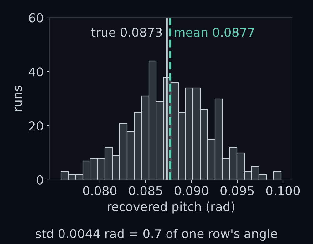
The pitch recovered by 500 calibrations from the four marks, each with random row errors of standard deviation 0.5 px, as a histogram. They centre on 0.0877 rad, next to the true 0.0873 rad, with a standard deviation of 0.0044 rad, 0.7 of one row's angle.
Figure 22. The pitch recovered by 500 calibrations from the four marks, each with random row errors of standard deviation 0.5 px, as a histogram. They centre on 0.0877 rad, next to the true 0.0873 rad, with a standard deviation of 0.0044 rad, 0.7 of one row's angle.

3. With w = 1 the ray picks up t, so its height part is 1.4−(sin⁡φ+bcos⁡φ)1.4 - (\sin\varphi + b\cos\varphi). That is negative only when b > (1.4 − sin φ) / cos φ, which is row 300.4. The picture's bottom edge, row 179.5, has b = 0.5625, so no pixel's ray points down.

4. The box computes λ from its assumed 1.4 m, so its ground point is (1.4/h)(1.4/h) times the one the ray truly reaches, and both the forward and the sideways parts scale by the same factor. Over 200 random road points the box's forward and sideways distances are 1.166667 times the truth for h = 1.2 and 0.875 times for h = 1.6, with no exceptions. Scaling a picture keeps its angles, which is why the heading survives.

Go deeper

Lab

Write the box in Colab and run its checks. Come back here for the quiz.

Open lab in Colab

Checkpoint quiz

1.

The ego frame has xx forward and yy to the left. For a right-handed frame, which way must zz point? Check it with the cross product forward ×\times left.

2.

A positive turn about the car's yy axis (pointing to its left) follows the right-hand rule. What does it do to the car's nose?

3.

The camera's mount turn is Ry(φ) B⊤R_y(\varphi),B^\top. Someone writes the product in the other order, B⊤Ry(φ)B^\top R_y(\varphi). What camera is that?

4.

A pixel's ray, in ego numbers, is (0.9632,−0.5937,−0.4638)(0.9632, -0.5937, -0.4638), and the lens is 1.41.4 m above the road. How many steps λ\lambda down the ray reach the road? (Give a decimal.)

5.

The car's forward direction, in camera numbers, is (0,−0.0872,0.9962)(0, -0.0872, 0.9962). In which picture row does it land? Use v=89.5+160 y/zv = 89.5 + 160,y / z. (Give a decimal row.)

6.

The camera is really tipped 5°5° up, but the box assumes 5°5° down. Which roads show it?

Teach it back

Explain this week as if to a friend who has never seen it. Then paste it, with the prompt below, into any AI tutor and ask it to find the gaps.

Show the tutor prompt
You are a Socratic tutor for unit 1.1.5 "The camera's point of view" of a self-driving car course. I am a programmer with rusty maths and no machine-learning background. I have just read a lecture and done a lab on the camera's mount and on where each pixel looks on the road.

What the unit taught (use these facts exactly):
- The ego frame is right-handed in 3D: x forward, y left, z up, origin on the road under the front axle. forward x left = up. A positive turn about an axis follows the right-hand rule: about z it is a left turn (yaw theta), about y it tips the nose DOWN (pitch phi), about x it tips left toward up (roll).
- rot_y(phi) sends forward (1, 0, 0) to (cos phi, 0, -sin phi). The camera's phi = 0.0873 rad (5 degrees), so its lens axis in the ego frame is (0.9962, 0, -0.0872). The earlier perception lesson wrote this angle p; it is phi now.
- The optical frame: x right across the picture, y down it, z out through the lens. B = [[0,-1,0],[0,0,-1],[1,0,0]] takes ego numbers to cam numbers; B transpose takes them back. R_ego<-cam = rot_y(phi) times B transpose. The other order, B transpose times rot_y(phi), gives a camera looking level and 5 degrees to the right.
- T_ego<-cam is the 4 by 4 [[R_ego<-cam, t], [0 0 0, 1]] with t = (0, 0, 1.4). Its inverse has the last column (0, h cos phi, h sin phi) = (0, 1.3947, 0.122). With the given pinhole step u = cx + f x / z, v = cy + f y / z (f = 160, cx = 159.5, cy = 89.5) it reproduces the simulator's pixels to 0.0 px.
- Points take w = 1 (turned and shifted), directions w = 0 (turned only). Forward as a direction lands on the horizon, row 75.5. Treated as a point it lands at row 276.6, and then no pixel ray points down at all.
- A pixel's ray in cam numbers is ((u - cx)/f, (v - cy)/f, 1). Turned into ego numbers it is r; the road point is g = t + lambda r with lambda = -t_z / r_z, and NaN when r_z >= 0 (above the horizon). Pixel (254.5, 150), on the white line, gives r = (0.9632, -0.5937, -0.4638), lambda = 3.018, g = (2.907, -1.792).
- Misconception to probe: "a camera tipped the wrong way would show up on any road". Tipped 5 degrees up while the box assumes 5 down, the car finishes straight (mean 0.004 m from the lane centre) but leaves gentle at 86.3 m, 13.7 m before the first bend: the far band places road 20 to 70 m ahead only 5.6 to 7.1 m ahead, so the coming bend reads as a sharp turn and the box reports a heading pointing right.
- A height error only scales: a camera truly 1.2 m up, read as 1.4 m, puts every road point 7/6 as far away, and angles survive.

How to run the session:
1. Ask me ONE question at a time, then wait for my answer. Start by asking me which way z must point so that the ego frame is right-handed, and how I would check it with a cross product.
2. Never give me the answer. If I am wrong or vague, ask a smaller question, or give me numbers to work through by hand, so I find the mistake myself.
3. Within the first three questions, test the misconception: ask which road, straight or gentle, would reveal a camera tipped up instead of down, and why.
4. Ask at least one question where I write a point in the optical frame from ego numbers, one where I compute lambda and the road point for a ray you give me, and one where I explain why a direction must use w = 0.
5. Keep your turns short: two or three sentences, then the question.
6. After about five exchanges, stop. List what I explained well, and what I should revisit, naming these lecture sections: "A third axis", "Turning about each axis", "The camera's own axes", "One 4×4 for the mount", "Points move, directions only turn", "Where a pixel's ray meets the road", "A camera mounted wrong".

Pilot log

0 logged

Saved in this browser. It tells the course author where this week is hard.

Confidence (1 = lost, 5 = could teach it)